Abstract
This research explores the dynamic response of layered metal-composite shields subjected to high-velocity impacts, utilizing both finite element analysis (FEM) and physical experimentation with the RAFTAR Railgun. The Johnson-Cook (JC) plasticity and failure models were employed to simulate material behaviour under extreme conditions. The study focused on optimizing the shield's material composition and layering sequence, using a combination of Stainless Steel 304 (SS 304), Aluminum 6061‑T6 (Al 6061‑T6), and Glass Fiber Reinforced Polymer (GFRP).
Experiments were conducted using a high-velocity projectile launched by the RAFTAR Railgun, and simulations mirrored these conditions to validate the accuracy of the FEM models. The projectile, composed of Aluminum 7075‑T6, was subjected to impact velocities of up to 1000 m/s, while the shields' performance was analyzed in terms of energy absorption, material deformation, and projectile penetration.
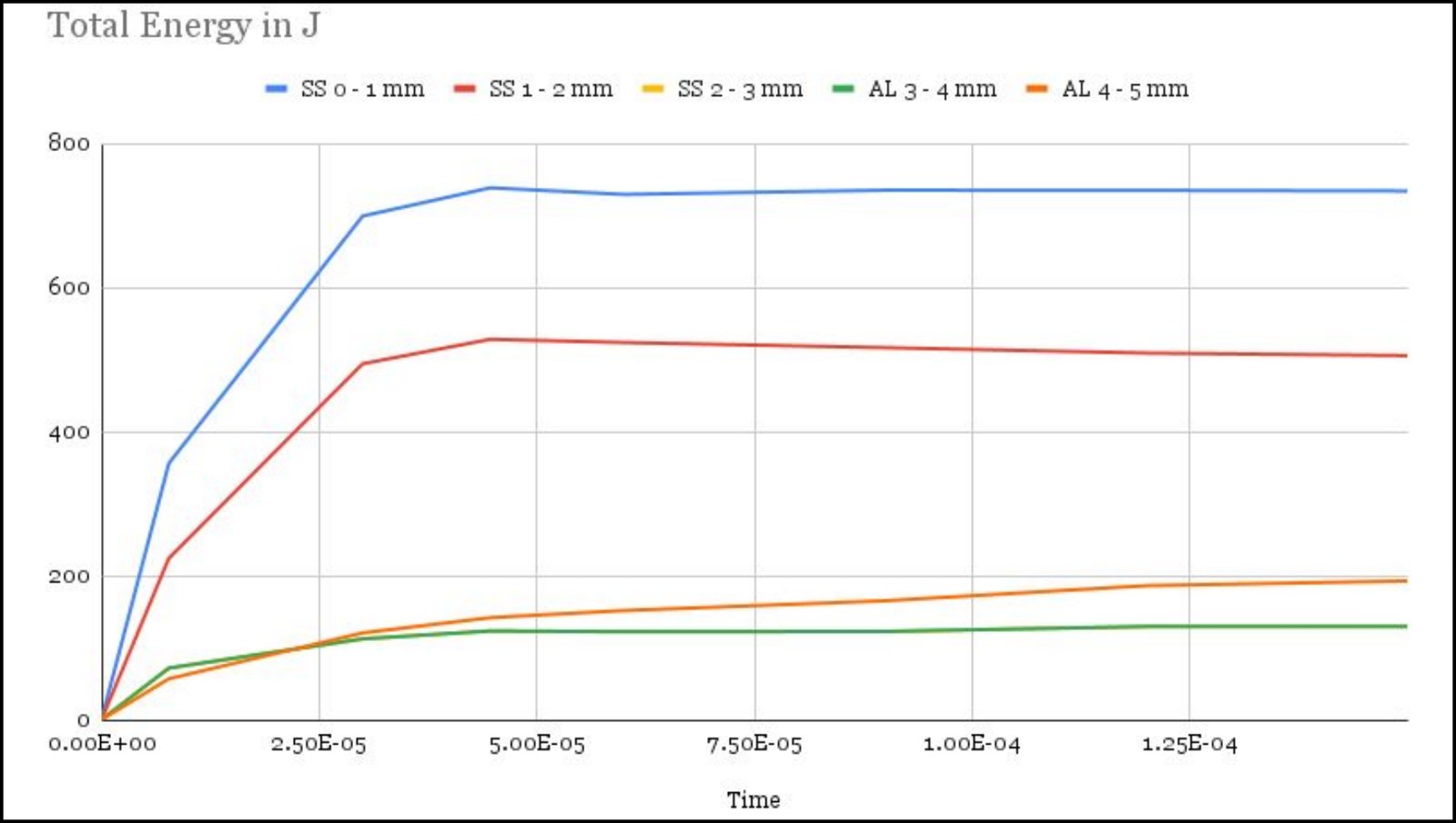
The results showed that 4 mm of SS 304 stopped the projectile at 1000 m/s, and that a layered SS 304 (3 mm) – Al 6061‑T6 (2 mm) composite was the most effective lighter alternative, whereas configurations containing GFRP were perforated. Inferences have been drawn regarding the composite materials' energy absorption capacity and failure mechanisms, highlighting the strategic effectiveness of material layering in mitigating high-velocity impact damage. The findings offer valuable insights for designing impact-resistant composite systems in defence and aerospace applications.
Keywords: High-Velocity Impact, Electromagnetic Railgun, Johnson-Cook Model, Finite Element Analysis, Layered Composite Shields, SS 304, Al 6061‑T6, GFRP
Key results
Poster
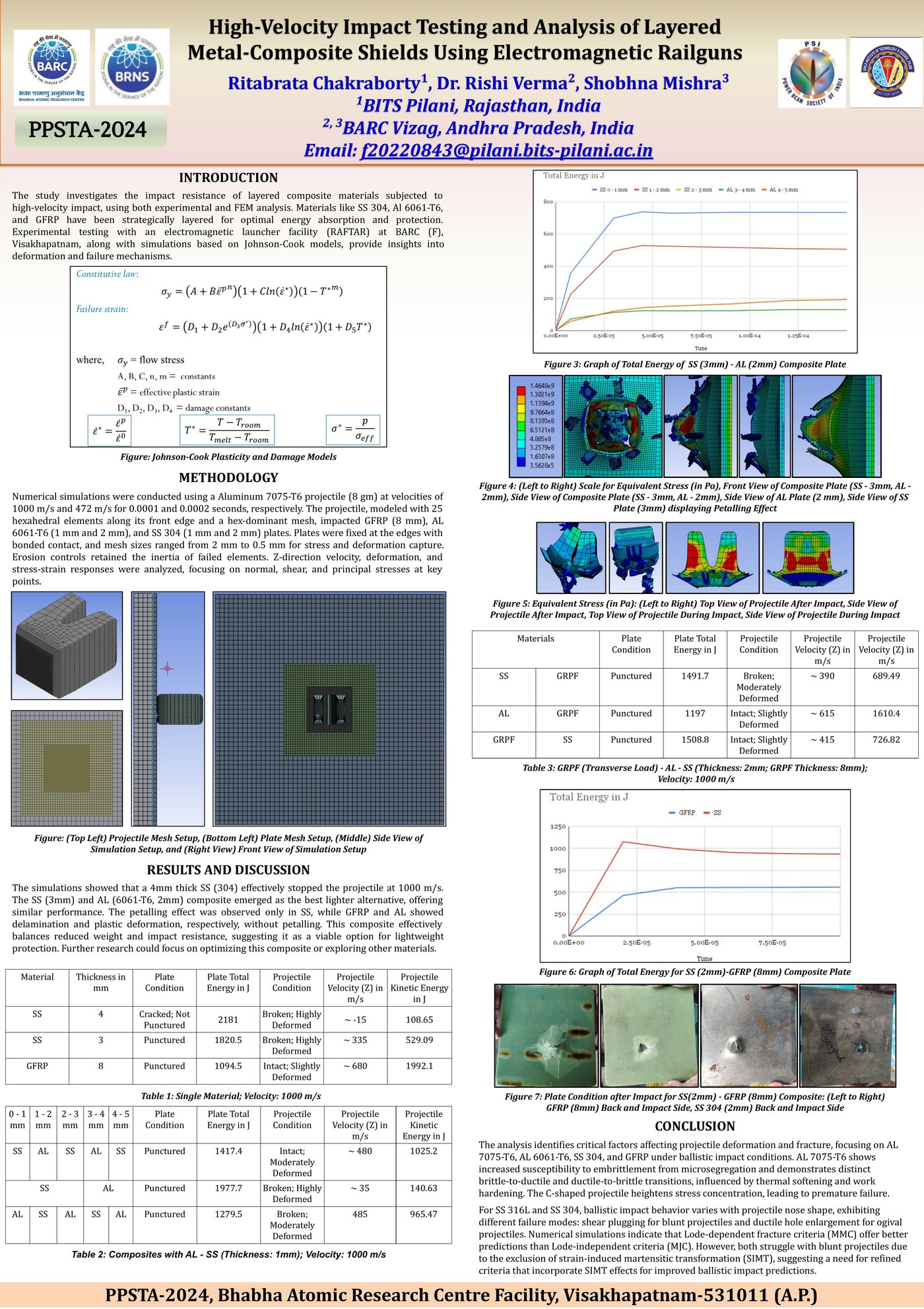
A0 poster, PPSTA-2024. Open the full-resolution PDF.
Method
Experiments used the RAFTAR electromagnetic launcher facility at BARC Facility, Visakhapatnam. Numerical simulations modelled an Al 7075‑T6 projectile (8 g) at 1000 m/s and 472 m/s, over 0.0001 s and 0.0002 s respectively. Target plates were GFRP (8 mm), Al 6061‑T6 (1 mm and 2 mm) and SS 304 (1 mm and 2 mm), fixed at the edges with bonded contact between layers.
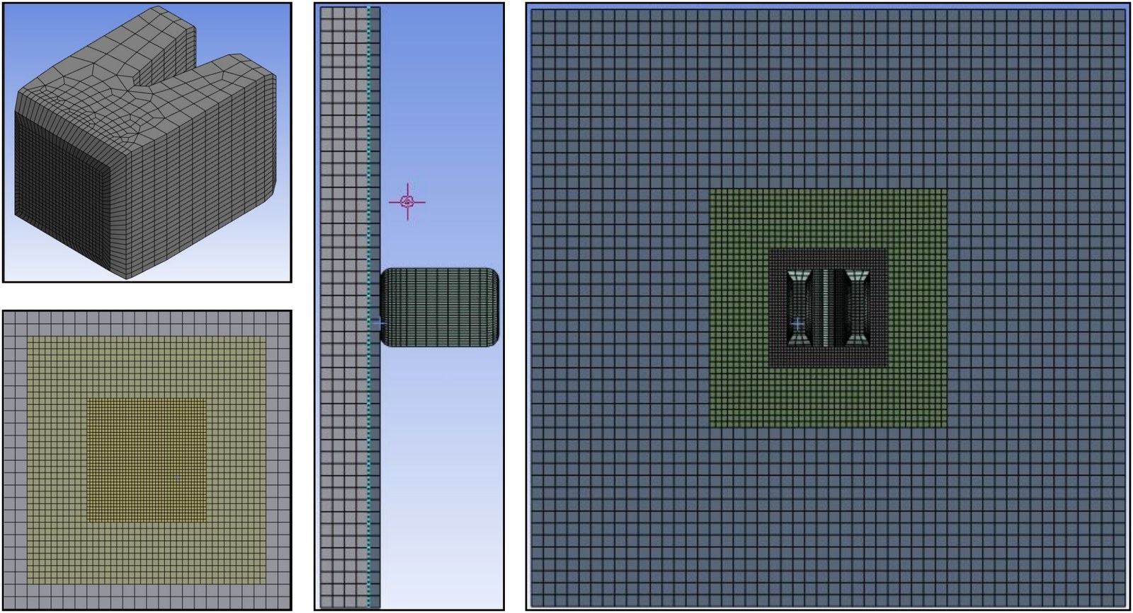
The projectile was meshed with 25 hexahedral elements along its front edge and a hex-dominant mesh elsewhere. Plate mesh sizes ranged from 2 mm to 0.5 mm to capture stress and deformation, and erosion controls retained the inertia of failed elements. Z-direction velocity, deformation and stress–strain responses were analysed, focusing on normal, shear and principal stresses at key points.
Johnson-Cook plasticity
\[ \sigma_y = \left(A + B\,\bar{\varepsilon}_p^{\,n}\right)\left(1 + C\ln\dot{\varepsilon}^{*}\right)\left(1 - T^{*m}\right) \]Johnson-Cook failure strain
\[ \varepsilon^{f} = \left(D_1 + D_2\,e^{D_3\sigma^{*}}\right)\left(1 + D_4\ln\dot{\varepsilon}^{*}\right)\left(1 + D_5T^{*}\right) \] \[ \dot{\varepsilon}^{*} = \frac{\dot{\varepsilon}_p}{\dot{\varepsilon}_0}, \qquad T^{*} = \frac{T - T_{\text{room}}}{T_{\text{melt}} - T_{\text{room}}}, \qquad \sigma^{*} = \frac{p}{\sigma_{\text{eff}}} \]\(\sigma_y\): flow stress; \(\bar{\varepsilon}_p\): effective plastic strain; \(A, B, C, n, m\): material constants; \(D_1\)–\(D_5\): damage constants.
Results
Table 1: Single-Material Plates; Impact Velocity 1000 m/s
| Material | Thickness (mm) | Plate Condition | Plate Total Energy (J) | Projectile Condition | Projectile Velocity, Z (m/s) | Projectile KE (J) |
|---|---|---|---|---|---|---|
| SS 304 | 4 | Cracked; Not Punctured | 2181 | Broken; Highly Deformed | ≈ −15 | 108.65 |
| SS 304 | 3 | Punctured | 1820.5 | Broken; Highly Deformed | ≈ 335 | 529.09 |
| GFRP | 8 | Punctured | 1094.5 | Intact; Slightly Deformed | ≈ 680 | 1992.1 |
Al–SS Composites
Table 2: Al 6061‑T6 / SS 304 Composites Built from 1 mm Layers (5 mm Total; Columns Give Layer Depth in mm); Impact Velocity 1000 m/s
| 0–1 | 1–2 | 2–3 | 3–4 | 4–5 | Plate Condition | Plate Total Energy (J) | Projectile Condition | Projectile Velocity, Z (m/s) | Projectile KE (J) |
|---|---|---|---|---|---|---|---|---|---|
| SS | Al | SS | Al | SS | Punctured | 1417.4 | Intact; Moderately Deformed | ≈ 480 | 1025.2 |
| SS | Al | Punctured | 1977.7 | Broken; Highly Deformed | ≈ 35 | 140.63 | |||
| Al | SS | Al | SS | Al | Punctured | 1279.5 | Broken; Moderately Deformed | 485 | 965.47 |
GFRP Composites
Table 3: GFRP (Transverse Load) with Al 6061‑T6 or SS 304; Metal Layer 2 mm, GFRP 8 mm; Impact Velocity 1000 m/s
| Layer 1 | Layer 2 | Plate Condition | Plate Total Energy (J) | Projectile Condition | Projectile Velocity, Z (m/s) | Projectile KE (J) |
|---|---|---|---|---|---|---|
| SS | GFRP | Punctured | 1491.7 | Broken; Moderately Deformed | ≈ 390 | 689.49 |
| Al | GFRP | Punctured | 1197 | Intact; Slightly Deformed | ≈ 615 | 1610.4 |
| GFRP | SS | Punctured | 1508.8 | Intact; Slightly Deformed | ≈ 415 | 726.82 |
Corrections from the printed poster: “GRPF” is written GFRP, and the last column of Table 3, printed as a second velocity column, is labelled projectile kinetic energy to match its values and Tables 1–2.
Discussion
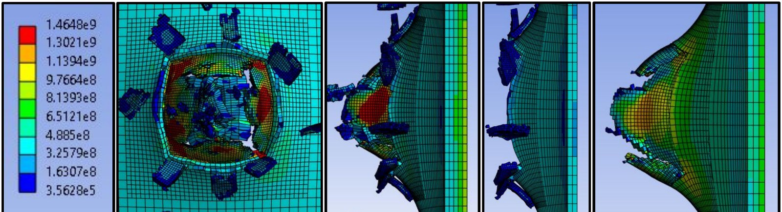
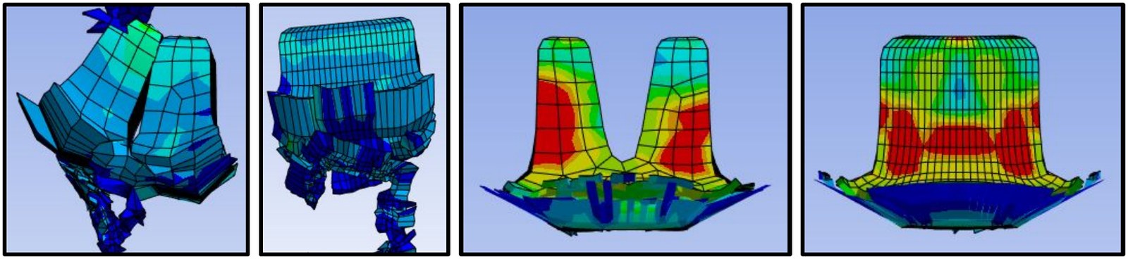
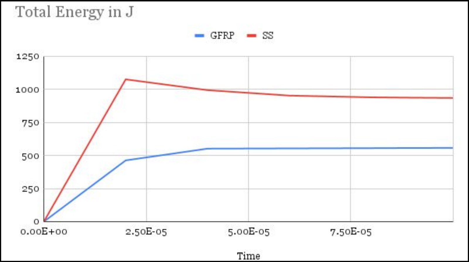
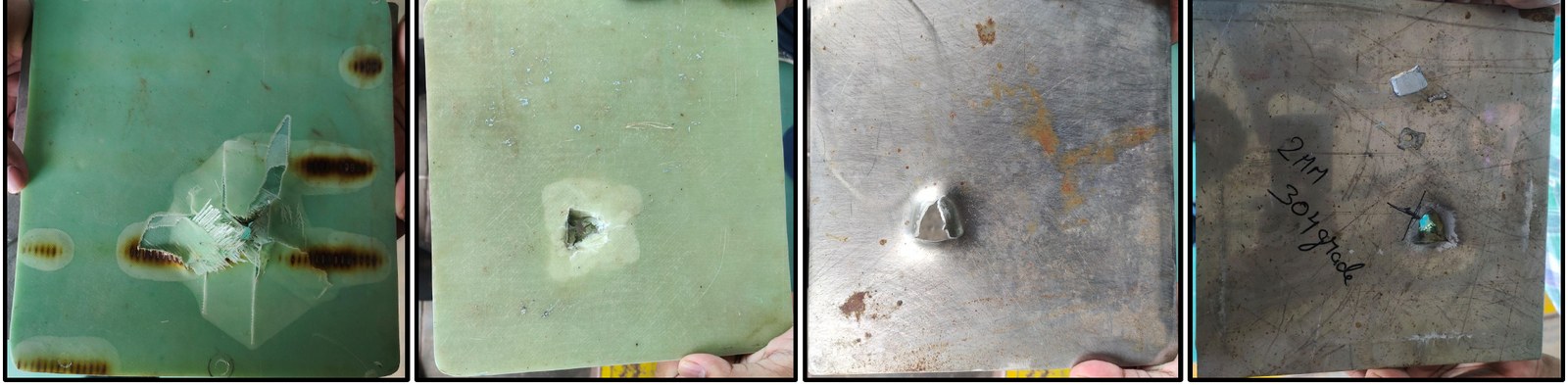
The simulations showed that a 4 mm SS 304 plate stopped the projectile at 1000 m/s. The SS 304 (3 mm) – Al 6061‑T6 (2 mm) composite was the best lighter alternative, with similar performance. Petalling was observed only in SS. GFRP failed by delamination and Al by plastic deformation, neither with petalling. This composite balances reduced weight against impact resistance, which makes it a viable option for lightweight protection. Further work could optimise this composite or explore other materials.
Conclusion
The analysis identifies critical factors affecting projectile deformation and fracture for Al 7075‑T6, Al 6061‑T6, SS 304 and GFRP under ballistic impact. Al 7075‑T6 is more susceptible to embrittlement from microsegregation and shows distinct brittle-to-ductile and ductile-to-brittle transitions, influenced by thermal softening and work hardening. The C-shaped projectile concentrates stress, leading to premature failure.
For SS 316L and SS 304, ballistic impact behaviour varies with projectile nose shape: blunt projectiles cause shear plugging, while ogival projectiles cause ductile hole enlargement. Numerical simulations indicate that Lode-dependent fracture criteria (MMC) predict better than Lode-independent criteria (MJC). Both struggle with blunt projectiles because they exclude strain-induced martensitic transformation (SIMT), so refined criteria that include SIMT effects are needed for better ballistic impact predictions.
Citation
@inproceedings{chakraborty2024railgun,
  title     = {High-Velocity Impact Testing and Analysis of Layered
               Metal-Composite Shields Using Electromagnetic Railguns},
  author    = {Chakraborty, Ritabrata and Verma, Rishi and Mishra, Shobhna},
  booktitle = {DAE-BRNS 1st National Conference on Pulsed Power Science,
               Technology and Applications (PPSTA-2024)},
  address   = {BARC Facility, Visakhapatnam, India},
  month     = sep,
  year      = {2024},
  note      = {Poster},
  url       = {https://robotics1106.github.io/Railgun-Impact-Layered-Shields/}
}